
Overview: Solid modeling is the process of creating and modifying solid objects. Each solid object has topology defining the surface area and volume of that object. Faces, edges, and vertices comprise the topology.
Advantages of Solid Modeling
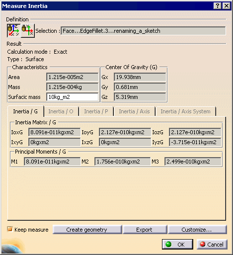
One of the main advantages of solid modeling is the ability to analyze the model. You can calculate detailed mass properties, such as weight, volume, and moment of inertia, for a solid body. You can also perform structural or fluid flow analysis, such as that of plastic injection molded parts.
Other advantages of solid modeling include:
- Creation of a 'virtual solid', geometrically identical to the actual part.
- Ability to rapidly create and change models.
- Powerful feature associativity and feature positioning.
- Greater ease in modifying designs.
- Drafting associativity with a solid model.
- Substantially improved design visualization.
- Mass properties information.
- Easy-to-create rapid-prototyping output.
- Evaluation of form, fit, and function.
- Associative manufacturing data.
- Using an assembly to design new components in the context of an entire product model.
- Checking interference between parts.
Design Intent
Design intent refers to the ability to capture geometric conditions, dimensional relationships, and relative positions between features on solid models.
Years ago, you did not have the ability to record the steps used in building a solid body. This process is known as explicit solid modeling. You create a solid body without capturing a history of the individual features used in its construction, which makes the process of modifying the solid body complex and time-consuming.
A CAD software application that can capture design intent is known as a 'parametric modeler'. CATIA has robust parametric modeling functions. The program also gives you a choice to add, or later remove, design intent. At the start of a design, you may not know what sort of design intent is necessary. By using parameters, positional constraints, instances, and feature editing, you can change or add design intent to the solid model.
Part Modeling
Feature Based Design